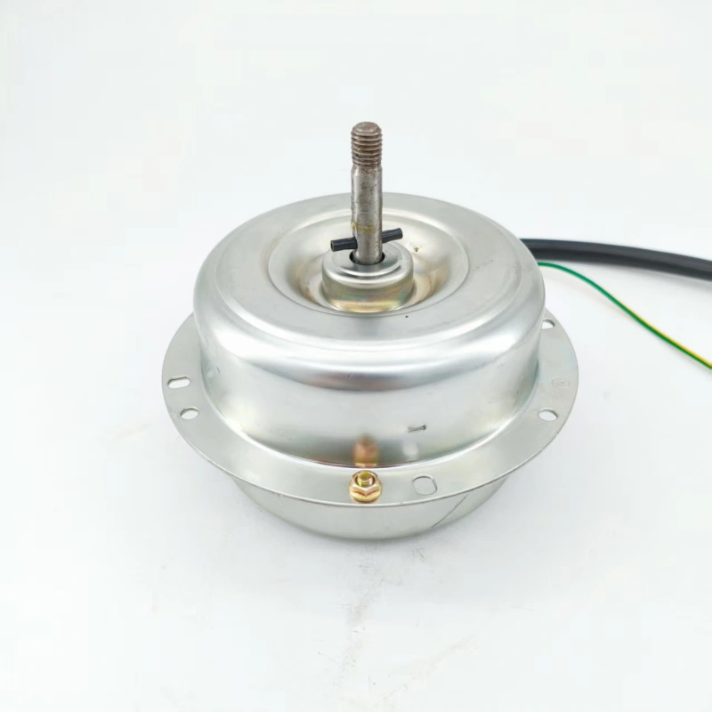
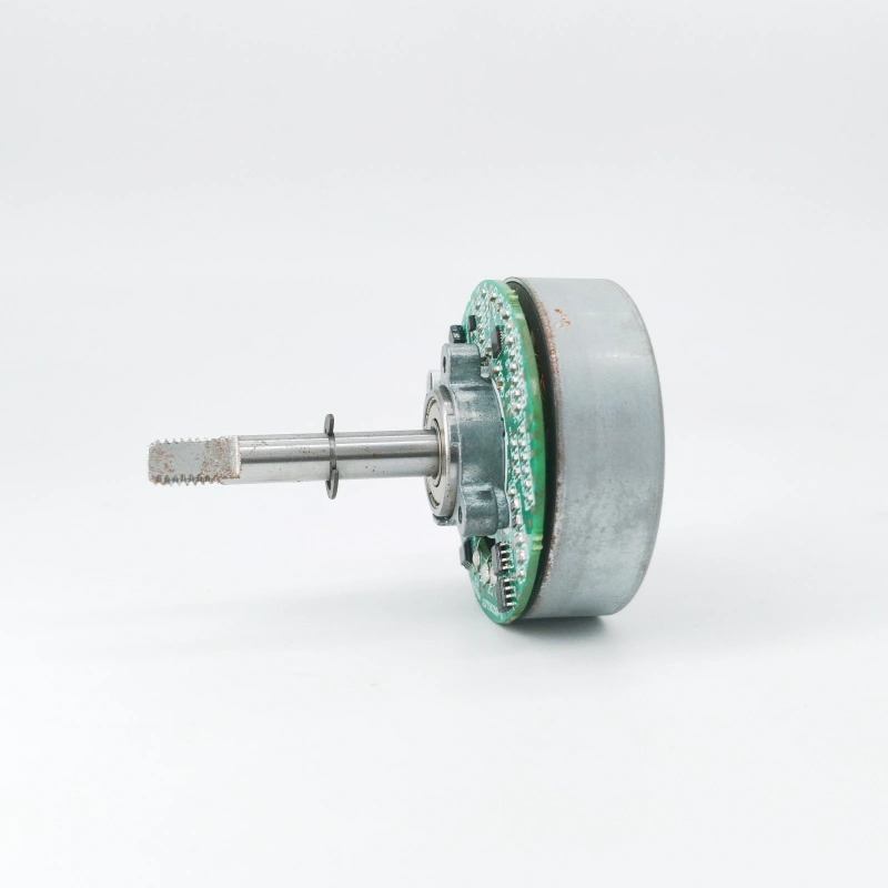
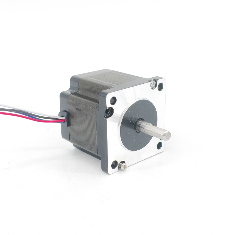
The reason an AC motor can achieve continuous rotation lies in its utilization of the principle of electromagnetic induction and the effect of a rotating magnetic field, along with a specific structural design that stably converts electrical energy into mechanical energy. Its key structures and working principles can be analyzed from the following two aspects:
1. Key Structures: The “Hardware Foundation” Supporting Rotation
An AC motor mainly consists of two major parts: the stator and the rotor. The collaborative operation of these two parts is a prerequisite for realizing rotation.
- Stator: As the fixed part of the motor, the core components of the stator are the stator core and the stator winding. The stator core is usually formed by laminating silicon steel sheets, which can effectively reduce eddy current losses. The inner side of the core is evenly distributed with slots for embedding the stator winding. The stator winding is generally made of enameled copper wires and connected into a three-phase winding according to specific rules (most industrial AC motors are three-phase motors), which is connected to a three-phase AC power supply. When current is passed through the winding, the stator generates a rotating magnetic field, which serves as the “power source” driving the motor to rotate.
- Rotor: The rotor is the rotating part of the motor and is commonly divided into two types: squirrel-cage rotor and wound rotor. The squirrel-cage rotor has a simple structure, consisting of a rotor core, rotor windings (copper bars or aluminum bars), and end rings. The rotor windings are embedded in the slots of the core like a “cage” and short-circuited at both ends through the end rings. The wound rotor, on the other hand, has windings with insulating layers embedded in the slots of the core. The two ends of the windings are led out through slip rings and brushes, and external resistors can be connected to adjust the motor’s performance. The core function of the rotor is to generate an induced current under the action of the stator’s rotating magnetic field, and then be pushed to rotate by electromagnetic force.
2. Working Principle: The “Rotation Logic” Driven by Electromagnetic Force
The rotation of an AC motor relies on a complete process of “rotating magnetic field generation – induced current formation – electromagnetic force-driven rotation”. Taking the three-phase asynchronous AC motor (the most widely used type) as an example:
- Generation of Rotating Magnetic Field: When the three-phase windings of the stator are connected to a symmetric three-phase AC power supply, each phase of the winding will generate an alternating current that changes sinusoidally with time. Due to the 120° phase difference between the three-phase currents, the combined magnetic field jointly excited by them in the stator core is not stationary but rotates around the motor’s axis at a stable speed (known as the synchronous speed), forming a “rotating magnetic field”. The magnitude of the synchronous speed is determined by the power supply frequency and the number of pole pairs of the motor’s stator winding, following the formula: n₀ = 60f/p (where n₀ is the synchronous speed, in r/min; f is the power supply frequency, in Hz; p is the number of pole pairs).
- Rotor Induced Current and Electromagnetic Force: The magnetic field lines of the rotating magnetic field will cut the rotor windings (or rotor bars). According to the law of electromagnetic induction, an induced electromotive force is generated in the rotor windings. Since the rotor windings form a closed circuit through the end rings (or external circuits), the induced electromotive force drives a current to flow in the rotor windings, generating a “rotor induced current”. At this point, the rotor conductors with induced current are in the stator’s rotating magnetic field. According to Fleming’s Left-Hand Rule, the rotor conductors are subjected to the action of electromagnetic force. The total torque exerted by these electromagnetic forces on the motor’s rotor axis is called the “electromagnetic torque”.
- Continuous Rotation and “Asynchronous” Characteristic: Driven by the electromagnetic torque, the motor’s rotor starts to rotate in the direction of the rotating magnetic field and gradually accelerates. However, it should be noted that the speed of the rotor (referred to as the rotor speed n) can never reach the synchronous speed n₀ of the stator’s rotating magnetic field. This is because if the rotor speed is equal to the synchronous speed, there will be no relative motion between the rotor conductors and the rotating magnetic field, and the magnetic field lines cannot cut the rotor conductors. As a result, both the rotor induced current and the electromagnetic torque will disappear, and the rotor will decelerate due to resistance. Therefore, the rotor speed is always lower than the synchronous speed. This “speed difference” is a necessary condition for maintaining the rotor induced current and electromagnetic torque, and it is also the origin of the name “asynchronous motor” (the ratio of the speed difference to the synchronous speed is called the slip rate s, where s = (n₀ – n)/n₀, and s is usually between 0.01 and 0.05 during normal operation). It is through this mechanism of “the rotating magnetic field driving the rotor and the speed difference maintaining power” that the AC motor achieves continuous and stable rotation, thereby driving various mechanical equipment to operate.


