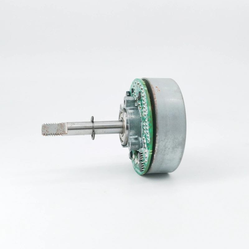
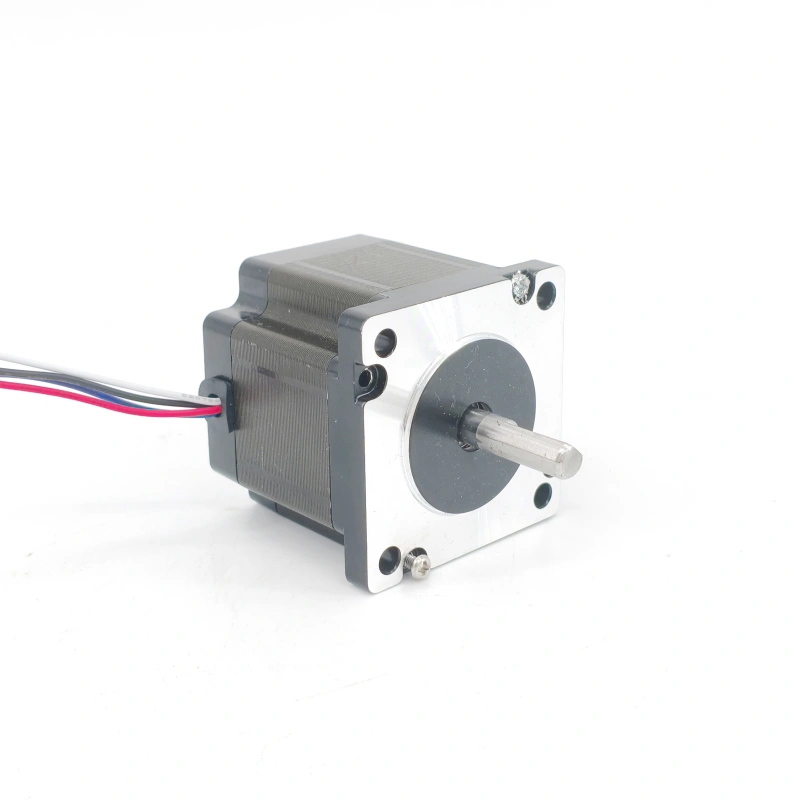
In frequent start-stop scenarios (e.g., elevators, CNC machine tools, automated production lines), DC motors undergo repeated transitions from 0 to rated speed and vice versa. This subjects specific components to constant impact and energy loss, requiring focused attention on four core components: brushes and commutators, armature windings, bearings, and electromagnetic brakes. Their wear mechanisms and targeted maintenance measures are detailed below:
1. Brushes and Commutators: High-Impact Zones for Friction and Sparking During Starts/Stops
Frequent starts and stops accelerate wear on brushes and commutators, driven by two key factors: First, armature current fluctuates drastically during starts/stops (starting current can reach 5–8 times the rated current), and the commutator speed rapidly ramps up or down from 0, causing “sliding friction impact” and “intensified commutation sparking” at the contact interface. On one hand, friction impact accelerates brush wear—under normal continuous operation, brushes typically last 2,000–3,000 hours, but this lifespan shortens to 800–1,200 hours in frequent start-stop scenarios. If brushes are not replaced when worn to 1/3 of their original length, contact area decreases, current density increases, and sparking worsens. On the other hand, sudden changes in commutation electromotive force during starts/stops easily generate strong sparks, which burn the commutator surface, creating pits or oxide layers and increasing contact resistance—forming a vicious cycle of “wear → sparking → more severe wear”.
Maintenance focuses on three key steps:
- Regularly inspect brush wear every 200–300 operating hours. Replace brushes with suitable models (e.g., graphite-metal powder composite brushes are preferred for frequent start-stop scenarios, as they offer 30% higher wear resistance than pure graphite brushes) and ensure brush pressure is stabilized at 15–25 kPa (insufficient pressure causes sparking; excessive pressure accelerates wear).
- Polish the commutator surface with 400-grit fine sandpaper every 500 hours to remove oxide layers and pits, ensuring surface roughness (Ra) ≤ 0.8 μm. Clean the surface with alcohol after polishing.
- Apply a thin layer of conductive grease (e.g., graphite-based grease) to the commutator surface to reduce friction coefficient during starts/stops and minimize sparking.
2. Armature Windings: Risks of Insulation Degradation and Copper Loss Under Start-Stop Current Impact
During starts and stops, armature windings face dual wear threats:
- High starting current causes a surge in copper loss (Pcu = I²R). For example, a motor with a rated current of 50 A may have a starting current of 300 A, increasing copper loss to 36 times the rated operating level. This causes a sudden temperature rise in the windings, accelerating insulation aging (e.g., the lifespan of Class B insulation is halved when exposed to temperatures above 130°C).
- As the rotor rotates, armature windings endure repeated electromagnetic force impacts. Particularly at the fixed ends of winding wires, vibration easily damages the insulation layer, leading to inter-turn short circuits.
Maintenance centers on “current control” and “insulation testing”:
- Install a soft starter in the armature circuit. By gradually increasing the armature voltage, the starting current is limited to 1.5–2 times the rated value (e.g., 75–100 A for a 50 A motor), avoiding high-current impacts.
- Test the insulation resistance of armature windings with a megohmmeter every 3 months, ensuring it remains ≥ 0.5 MΩ (for 380 V motors). If insulation resistance drops, disassemble the motor and dry the windings with a heat gun (temperature ≤ 80°C) or reapply insulating paint (e.g., epoxy-modified insulating paint).
- Inspect the binding tape at the ends of armature windings. Replace loose or broken tape with high-temperature-resistant alternatives (e.g., fiberglass cloth tape) to prevent vibration-induced wear.
3. Bearings: Hidden Risks of Radial Force and Lubrication Failure During Starts/Stops
Frequent starts and stops disrupt the stable lubrication and force balance of bearings:
- At startup, the rotor accelerates suddenly from rest, causing “sliding friction” (instead of normal rolling friction) between the bearing inner ring and balls. This breaks the grease film, accelerating wear on balls and raceways.
- During starts/stops, the motor shaft is prone to radial runout due to load fluctuations, subjecting bearings to additional radial force. Over time, this increases bearing clearance (normal deep-groove ball bearings have a clearance ≤ 0.1 mm, which may exceed 0.2 mm after frequent starts/stops), leading to abnormal noise and vibration.
Maintenance emphasizes “lubrication management” and “clearance testing”:
- Shorten the grease replacement interval—from 6 months (for normal operation) to 3 months for frequent start-stop scenarios. Use high-temperature, shear-resistant grease (e.g., Grade 2 composite lithium-based grease, suitable for -20°C to 150°C) and fill 1/2–2/3 of the bearing internal space (excessive grease causes overheating; insufficient grease leads to dry friction).
- Monitor bearing noise with a stethoscope every 200 hours. If “hum” or “clicking” sounds occur, shut down the motor immediately. Measure bearing clearance with a feeler gauge and replace bearings if clearance exceeds 0.15 mm.
- Ensure the coaxiality deviation between the motor shaft and coupling is ≤ 0.1 mm during installation to reduce radial force impact during starts/stops.
4. Electromagnetic Brakes: Wear on Brake Pads and Coils Under Frequent Braking
Some DC motors (e.g., elevator traction motors, hoist motors) are equipped with electromagnetic brakes. Frequent starts and stops require the brake to repeatedly “engage and disengage”, causing two types of wear:
- Brake pad wear: Each braking cycle involves friction between the pad and brake drum. Frequent braking reduces pad thickness rapidly (normal pad thickness is 5 mm; wear may reach 0.5–1 mm per month in frequent start-stop scenarios). When thickness drops below 2 mm, braking performance degrades significantly.
- Coil wear: Frequent energization of the brake coil increases copper loss. Additionally, electromagnetic force impact during engagement easily damages the coil insulation layer, leading to short circuits.
Maintenance targets “brake pads” and “coils”:
- Inspect brake pad thickness weekly. Replace pads when thickness is below 2 mm, ensuring ≥ 90% contact area between the pad and brake drum to avoid uneven force during braking.
- Measure brake coil resistance monthly. If deviation from the rated value exceeds 5%, disassemble the coil to check for inter-turn short circuits. Rewind the coil or replace the entire brake assembly if short circuits are detected.
- Apply a thin layer of high-temperature wear-resistant coating (e.g., ceramic-based coating) to the brake drum surface to improve wear resistance of pads and drums, extending pad lifespan.
In summary, for DC motors in frequent start-stop scenarios, “high-frequency inspections + targeted maintenance” of brushes/commutators, armature windings, bearings, and electromagnetic brakes can reduce component failure rates by over 60%. This ensures long-term stable operation and avoids production downtime or safety accidents caused by component damage.


