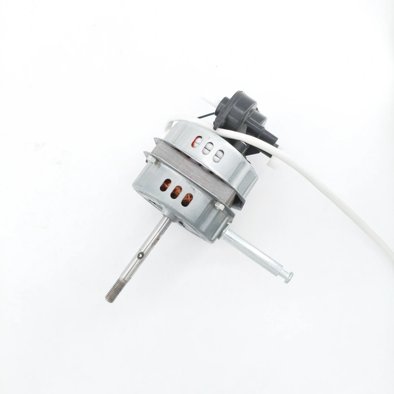
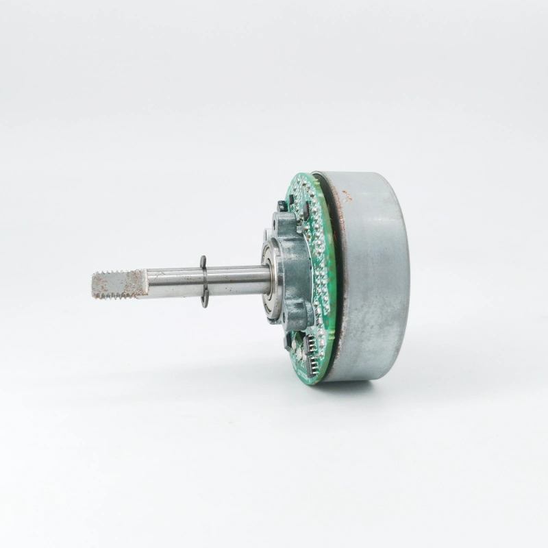
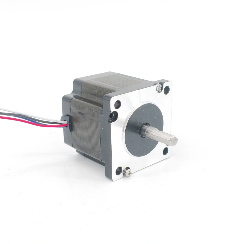
Abnormal vibration in AC motors during operation not only produces harsh noise but also accelerates bearing wear, causes damage to winding insulation, and may even lead to equipment shutdown failures. Its causes need to be analyzed from multiple dimensions such as mechanical structure, electromagnetic characteristics, and installation & maintenance, and targeted inspection and resolution must be carried out in combination with specific scenarios.
1. Mechanical Structure Imbalance: The Most Fundamental and High-Frequency Cause
- Rotor Dynamic Balance Failure
The rotor is the core component of the motor that rotates at high speed. If the metal material is unevenly distributed during manufacturing, the fan blades are deformed or the counterweight blocks fall off after long-term operation, or the rotor core is worn or the winding binding is loose during maintenance, the center of gravity of the rotor will deviate from the rotation axis, generating periodic centrifugal force and causing vibration.
Inspection Method: After cutting off the power supply, manually rotate the rotor to check for jamming or a sense of uneven weight. If the vibration of the motor intensifies with the increase of rotational speed when under load (e.g., the vibration significantly increases when the speed exceeds 1500 r/min), it is highly likely a dynamic balance problem.
Resolution Measure: Remove the rotor and send it to a professional institution for dynamic balance testing. Correct the imbalance by adding counterweight blocks or grinding the overweight parts. If the rotor windings are loose, re-bind them with non-woven tape and apply insulating paint for curing.
- Bearing Wear or Lubrication Failure
Bearings are key components connecting the rotor and stator. When the bearing balls/raceways are worn, the cage is broken, or the grease dries up or is contaminated with impurities, the rotor will experience radial or axial movement, resulting in “clunking” vibration, which is often accompanied by heating of the bearing (temperature exceeding 70°C).
Inspection Method: Use a stethoscope to listen closely to the bearing end cover. If irregular “rustling” or “impact sounds” are heard instead of the uniform “hum” during normal operation, a bearing failure can be determined. At the same time, check for grease leakage traces on the bearing end cover.
Resolution Measure: After shutting down the motor, remove the bearing end cover and replace the bearing with a high-precision one of the same model (e.g., deep groove ball bearing series 6205). Fill it with suitable high-temperature grease (e.g., lithium-based grease) with a filling amount of 1/2 to 2/3 of the internal space of the bearing to avoid over-filling or under-filling.
2. Abnormal Electromagnetic Characteristics: Directly Related to Motor Electrical Parameters
- Stator Winding Inter-Turn Short Circuit or Three-Phase Current Imbalance
If the stator windings have inter-turn short circuits due to insulation aging, moisture, or foreign object impact, the three-phase magnetic field distribution will be uneven, generating “unilateral magnetic pull” that causes the rotor to deviate to one side and trigger vibration. In addition, unbalanced three-phase power supply voltage (with a difference exceeding 5%) or incorrect winding connection (e.g., star connection mistakenly connected as delta connection) can also lead to three-phase current imbalance and exacerbate magnetic field disorder.
Inspection Method: Use a multimeter to measure the DC resistance of the three-phase stator windings. If the resistance value of one phase is more than 10% lower than that of the other two phases, there may be an inter-turn short circuit. Use a clamp ammeter to measure the three-phase current during operation. If the difference exceeds 10%, check the power supply voltage or wiring.
Resolution Measure: If the short-circuit point is obvious (e.g., blackened or charred windings), partially replace the winding coils and re-impregnate them with paint for drying. If the three-phase current imbalance is caused by the power supply, coordinate with the power department to adjust the voltage or install a three-phase voltage balancer at the motor input end.
- Uneven Air Gap: Deviation in the Gap Between Stator and Rotor
If the air gap (usually 0.2-1.5 mm) between the inner circle of the motor stator and the outer circle of the rotor is uneven due to frame deformation or misalignment of the end cover installation, the local magnetic flux density will be too high, resulting in periodic electromagnetic vibration. The vibration frequency is related to the power supply frequency (e.g., under a 50 Hz power supply, the vibration frequency is approximately 100 Hz).
Inspection Method: After shutting down the motor, use a feeler gauge to measure the air gap at 4 equally divided points on the rotor circumference. If the difference between the maximum and minimum air gaps exceeds 0.2 mm, the air gap is uneven. At the same time, check whether the frame is deformed or the end cover bolts are loose.
Resolution Measure: Loosen the end cover bolts and gently tap the end cover with a copper hammer to adjust its position until the air gap is uniform. If the frame is deformed, correct it with a press or replace the frame to ensure the coaxiality of the stator and rotor.
3. Installation and Load Matching Issues: Indirect Influences of External Factors
- Coaxiality Deviation Between Motor and Load Equipment
When the motor is connected to loads such as pumps and fans through couplings or pulleys, if the axes of the two are not concentric (radial deviation exceeding 0.1 mm or angular deviation exceeding 0.5°), additional radial pull will be generated during operation, causing motor vibration. The vibration will intensify as the load increases.
Inspection Method: Attach a dial indicator to the motor coupling and rotate the coupling for one full circle. If the swing range of the dial indicator pointer exceeds 0.1 mm, the coaxiality is substandard. In the case of belt transmission, obvious belt deviation or slipping may also be caused by axis deviation.
Resolution Measure: Adjust the installation position of the load equipment and correct the coaxiality between the motor and the load by adding or removing gaskets. For belt transmission, ensure that the grooves of the two pulleys are aligned and the belt tension is appropriate (the deflection should be 10-15 mm when pressing the belt).
- Unstable Foundation Installation or Resonance
If the motor is installed on a loose concrete foundation or the foundation has insufficient rigidity (e.g., thin steel plate bracket), the vibration amplitude will be amplified. In addition, if the motor operating frequency is close to the natural frequency of the foundation and load (resonance frequency), a “resonance phenomenon” will occur, leading to a sharp increase in vibration.
Inspection Method: Observe whether the foundation shakes obviously when the motor is running, or use a vibration detector to measure the vibration frequency. If it is close to the frequency corresponding to the motor’s rated speed (e.g., 1500 r/min corresponds to 25 Hz), resonance may exist.
Resolution Measure: Reinforce the foundation (e.g., increase the thickness of concrete, install shock-absorbing pads). If resonance is obvious, adjust the motor speed (e.g., replace the frequency converter to change the frequency) or install damping blocks on the foundation to avoid the resonance frequency range.
In summary, the inspection of abnormal vibration in AC motors should follow the principle of “mechanical first, then electromagnetic; external first, then internal”. Through sensory judgment (listening, looking, touching) combined with instrument testing, the cause can be accurately identified. After resolution, a no-load test run should be conducted for 30 minutes to confirm that the vibration value is below the national standard (e.g., the vibration velocity limit specified in GB 10068-2020) before resuming load operation to prevent repeated failures.


