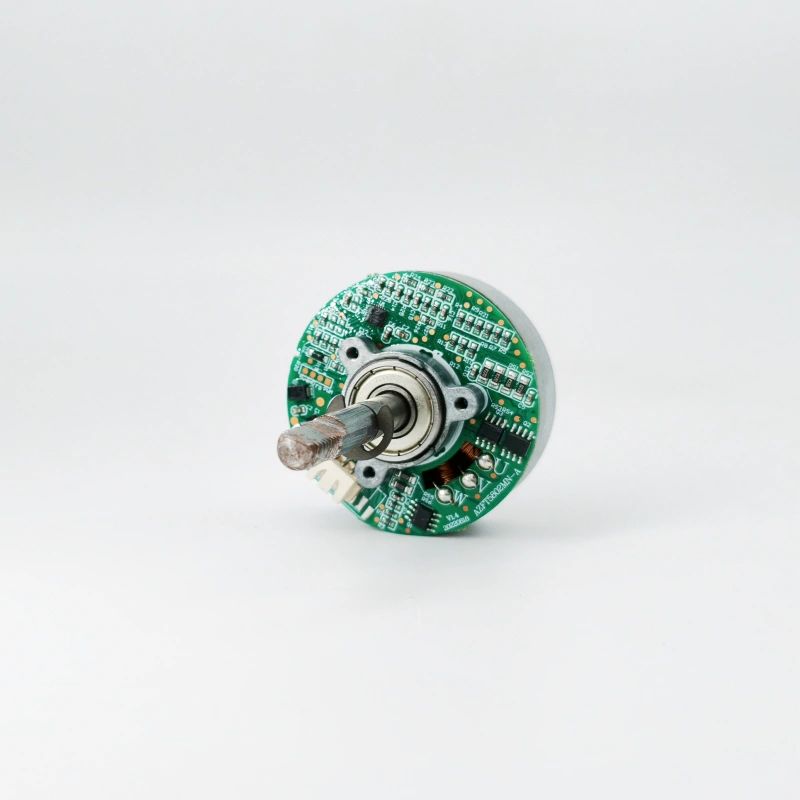
Động cơ DC là một thiết bị điện từ chuyển đổi năng lượng điện một chiều thành năng lượng cơ học (động cơ điện) hoặc ngược lại (máy phát điện). Nguyên lý hoạt động cốt lõi của nó dựa trên hai định luật điện từ cơ bản: định luật cảm ứng điện từ (chế độ máy phát điện) và quy tắc bàn tay trái (chế độ động cơ điện).
Dưới đây, cơ chế hoạt động sẽ được phân tích chi tiết theo bốn chiều: nguyên lý cốt lõi, cấu trúc chính, quy trình làm việc (chia thành động cơ/máy phát điện) và công nghệ cốt lõi (bộ chuyển mạch).
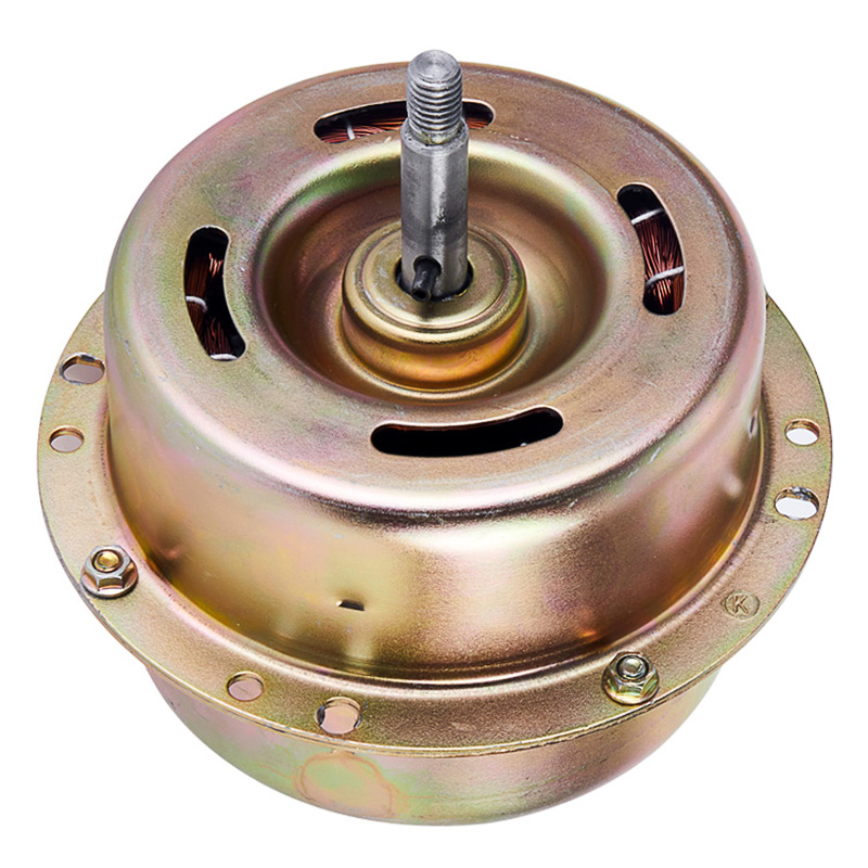
Để đảm bảo chuyển đổi ổn định “lực điện từ”, động cơ DC cần có năm thành phần cốt lõi sau, mỗi thành phần có chức năng liên kết với nhau:
Stato: Được cố định bên trong vỏ, thường bao gồm nam châm vĩnh cửu (động cơ công suất nhỏ) hoặc cuộn dây kích thích (động cơ công suất lớn), tạo ra từ trường ổn định (từ trường chính) và đóng vai trò là "nguồn từ trường" cho các hiệu ứng điện từ
Rotor: gồm nhiều cuộn dây (cuộn dây phần ứng) quấn quanh lõi sắt, có thể quay quanh trục trung tâm. Chế độ động cơ: các cuộn dây được điều khiển quay bằng lực điện từ sau khi được cấp điện;
Chế độ máy phát điện: Cuộn dây quay để cắt đường cảm ứng từ và tạo ra dòng điện
Bộ góp: Một "cấu trúc vòng bán nguyệt" đồng trục (gồm nhiều vòng bán nguyệt bằng đồng, với số lượng khớp với số vòng của cuộn dây phần ứng) giúp giải quyết "vấn đề đổi chiều" của dòng điện/lực điện động khi rôto quay, đảm bảo rằng đầu ra (hoặc đầu vào) là dòng điện một chiều
Chổi điện: một bộ phận dẫn điện (thường là vật liệu than chì) được cố định trên stato, tiếp xúc chặt chẽ với bề mặt của bộ góp điện, để tạo ra kết nối dòng điện giữa “mạch cố định” (nguồn điện/tải bên ngoài) và “mạch quay” (cuộn dây phần ứng)
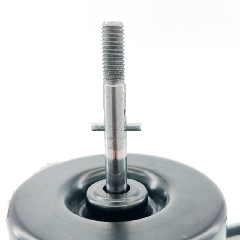
Vỏ và trục: Vỏ cố định stato, trục được kết nối với lõi sắt của rôto để hỗ trợ chuyển động quay của rôto, truyền năng lượng cơ học ra bên ngoài (động cơ điện) hoặc nhận năng lượng cơ học từ bên ngoài (máy phát điện)
3、 Giải thích chi tiết về quy trình làm việc (lấy “chế độ động cơ” phổ biến nhất làm ví dụ)
Cốt lõi của động cơ DC là "giữ cho rôto quay", nhưng nếu vấn đề về hướng không được giải quyết sau khi cuộn dây được cấp điện trong từ trường, rôto sẽ chỉ "quay một lần" và bị kẹt.
Sự phối hợp giữa bộ góp điện và chổi điện là chìa khóa để giải quyết vấn đề này và quy trình cụ thể được chia thành bốn bước:
1. Trạng thái ban đầu: Cuộn dây được cấp nguồn và kích hoạt bằng lực điện từ
Nguồn điện DC bên ngoài cung cấp điện cho bộ góp điện thông qua chổi than điện và dòng điện chạy vào một tập hợp các cuộn dây nhất định của rôto (chẳng hạn như cuộn dây AB).
Cuộn dây nằm trong từ trường do stato tạo ra (giả sử hướng của từ trường là “từ cực N đến cực S”), theo quy tắc bàn tay trái:
Phía AB của cuộn dây (gần cực N) sẽ chịu lực điện từ “hướng xuống”;
Cạnh CD của cuộn dây (gần cực S) sẽ chịu lực điện từ “hướng lên”;
Hai lực này tạo thành một “mô-men xoắn” khiến rô-to quay theo chiều kim đồng hồ quanh trục quay.
2. Các nút chính: Cuộn dây quay 90 ° và bộ góp điện chuyển đổi hướng của dòng điện
Khi rôto quay 90°, mặt phẳng cuộn dây “song song” với hướng của từ trường (mép cuộn dây không cắt đường cảm ứng từ), mômen điện từ bằng 0, nhưng rôto vẫn tiếp tục quay do quán tính.
Đồng thời, bộ góp điện quay đồng bộ với rôto, và nửa vòng tròn ban đầu tiếp xúc với “chổi điện cực dương” chuyển sang tiếp xúc với “chổi điện cực âm”;
Nửa vòng ban đầu được kết nối với điện cực âm đã được chuyển sang điện cực dương.
Kết quả: Chiều dòng điện trong cuộn dây bị đảo ngược (chẳng hạn dòng điện ở phía AB thay đổi từ “A → B” thành “B → A”).
3. Quay liên tục: Hướng của lực điện từ vẫn không đổi
Sau khi dòng điện đảo ngược, cuộn dây tiếp tục quay (trên 90°) và mép cuộn dây lại nằm trong từ trường.
Theo quy tắc bàn tay trái, mặc dù hướng của dòng điện đã thay đổi, nhưng vị trí của từ trường tại nơi cuộn dây đặt cũng đã thay đổi (phía AB bây giờ gần cực S hơn, phía CD gần cực N hơn) và hướng của lực điện từ vẫn không đổi (vẫn làm cho rôto quay theo chiều kim đồng hồ).
4. Lặp lại và lùi lại: đạt được vòng quay liên tục
Cứ mỗi vòng quay 180° của rôto, bộ góp điện sẽ hoàn thành một “chuyển mạch dòng điện”;
Đổi hai lần cho mỗi vòng quay 360°.
Thông qua 'chuyển mạch đồng bộ' này, cuộn dây luôn chịu 'mô-men xoắn dẫn động cùng hướng' và rôto đạt được sự quay liên tục và ổn định, cuối cùng chuyển đổi năng lượng điện DC thành năng lượng cơ học.


