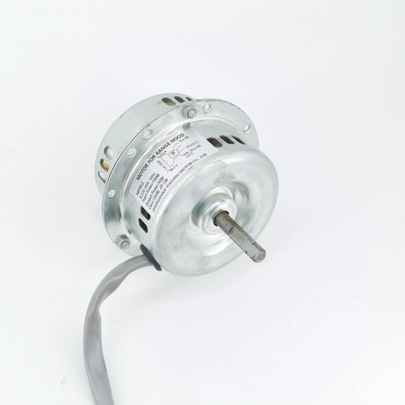
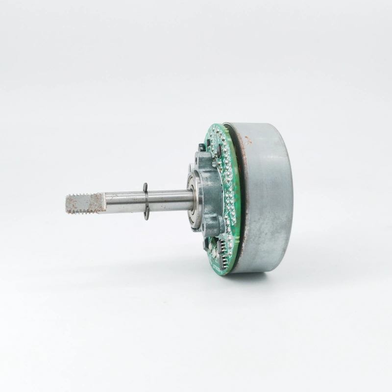
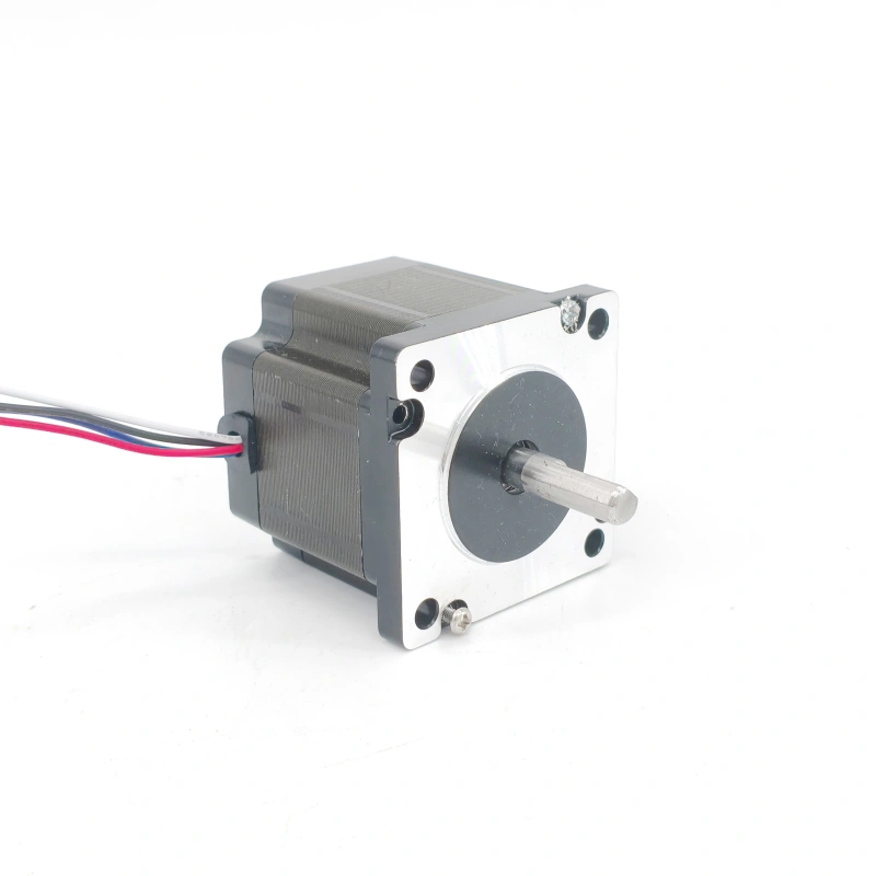
The core of controlling the speed of an AC motor lies in adjusting key input parameters of the motor, such as voltage, frequency, current, or magnetic field, based on the motor type (asynchronous motor / synchronous motor) and application scenarios (e.g., speed regulation accuracy, cost, energy consumption). Below is a detailed analysis of mainstream control methods, categorized by technical maturity and application scope:
I. Speed Regulation Based on “Voltage-Frequency Coordination” (Mainstream for Asynchronous Motors)
The speed formula of an asynchronous motor is: n = 60f(1-s)/p (where f = power supply frequency, s = slip ratio, p = number of motor pole pairs). By synchronously adjusting the “frequency f” and “stator voltage U”, wide-range and low-loss speed regulation can be achieved, making it the most commonly used solution in industry.
1. Variable Frequency Speed Regulation (VVVF, Variable Voltage Variable Frequency)
- Principle: Convert the industrial frequency AC power (e.g., 220V/50Hz, 380V/50Hz) into AC power with “adjustable voltage and frequency” through a “frequency converter” to meet the motor’s requirements for different speeds (an increase in frequency leads to an increase in speed, and vice versa).
- Key Logic: When the motor stator impedance is fixed, the U/f ratio must remain constant. Otherwise, it will cause magnetic flux saturation or insufficiency, resulting in motor burnout or reduced torque. Therefore, the frequency converter needs to coordinate voltage and frequency in real time.
- Classification:
- Scalar Control: Only controls the amplitude of voltage and frequency. It has a simple structure and low cost, and is suitable for scenarios with low requirements for speed regulation accuracy, such as fans, water pumps (e.g., outdoor units of household air conditioners).
- Vector Control: Decomposes the motor current into “excitation current” and “torque current”, and controls them accurately respectively to achieve high dynamic response similar to that of DC motors (e.g., CNC machine tools, elevator traction machines).
- Direct Torque Control (DTC): Skips current decomposition and directly controls the motor torque and flux linkage. It has a faster response speed and is suitable for high-dynamic scenarios such as rolling mills and servo systems.
- Advantages: Wide speed regulation range (0 to rated speed, even exceeding the rated speed), high efficiency (close to rated efficiency), and stable torque.
- Disadvantages: High cost of the frequency converter; harmonic interference may occur at high frequencies (a filter needs to be added).
2. Soft Starter Speed Regulation (Auxiliary Speed Regulation, Discontinuous Speed Regulation)
- Principle: Gradually increase the motor stator voltage through a thyristor (SCR) to achieve “smooth startup” and avoid large current impact during startup. Some soft starters support “voltage regulation-type speed regulation” (reduce the slip ratio s by lowering the voltage to indirectly reduce the speed).
- Application: Only applicable to “start-up phase” or “short-term, low-accuracy speed reduction” (e.g., light-load speed regulation of conveyor belts). It cannot achieve wide-range continuous speed regulation (excessively low voltage will cause the motor to overheat).
- Advantages: Lower cost than frequency converters; complete protection functions (overcurrent, overload).
- Disadvantages: Narrow speed regulation range (usually only can be reduced to 70% of the rated speed); low power factor at low speeds.
II. Speed Regulation Based on “Pole Pair Adjustment” (Variable-Pole Speed Regulation)
- Principle: According to the asynchronous motor speed formula n = 60f(1-s)/p, the synchronous speed of the motor is directly changed by altering the “number of pole pairs p” of the motor stator winding (e.g., 2 poles → 4 poles). At 50Hz, the synchronous speed of a 2-pole motor is 3000rpm, and that of a 4-pole motor is 1500rpm.
- Implementation Method: Change the current direction of the winding through a “commutation switch” (e.g., star-delta switching, double-star switching) of the motor winding, thereby changing the number of pole pairs.
- Application: Only applicable to “stepped speed regulation” scenarios (e.g., punch presses, compressors, fans). The motor must be designed to support multiple pole pairs (e.g., 2/4-pole, 4/6-pole two-speed motors).
- Advantages: Simple structure, low cost, reliable operation, and no efficiency loss during speed regulation.
- Disadvantages: Only “fixed-gear” speed regulation can be achieved (e.g., 2 gears, 3 gears); continuous and smooth speed regulation is not possible.
III. Speed Regulation Based on “Slip Ratio Adjustment” (Low-Accuracy, Low-Power Scenarios)
Speed regulation is achieved by changing the motor’s “slip ratio s” (the rate of difference between the actual speed and the synchronous speed). It is suitable for motors with low accuracy requirements and small power (e.g., household fans, small conveyors).
1. Stator Voltage Regulation Speed Regulation
- Principle: Reduce the stator voltage U through a voltage regulator (e.g., autotransformer, thyristor voltage regulation circuit), which reduces the motor torque T (T is proportional to U²). When the load torque remains unchanged, the slip ratio s increases, and the actual speed decreases.
- Advantages: Simple circuit and extremely low cost.
- Disadvantages: Narrow speed regulation range (only 10% – 30% speed reduction can be achieved); severe motor heating at low speeds (large slip power loss) and insufficient torque.
2. Rotor Series Resistance Speed Regulation (Applicable Only to Wound-Rotor Asynchronous Motors)
- Principle: The rotor winding of a wound-rotor asynchronous motor can be connected to an external resistor. By increasing the rotor circuit resistance R2, the slip ratio s is increased (s is proportional to R2), thereby reducing the actual speed (the synchronous speed remains unchanged, and an increase in slip leads to a decrease in actual speed).
- Application: Suitable for “short-term speed regulation” or “start-up speed regulation” scenarios (e.g., cranes, winches). It needs to be matched with a “rotor rheostat” to adjust the resistance value manually or automatically.
- Advantages: Simple structure, low cost, and stable torque during speed regulation (large starting torque).
- Disadvantages: Large rotor resistance loss at low speeds (electrical energy is converted into heat energy), low efficiency, and poor speed regulation accuracy (limited resistance gears).


