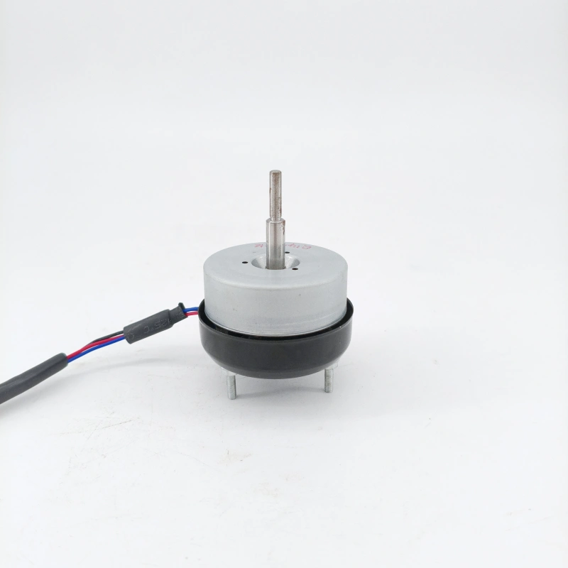
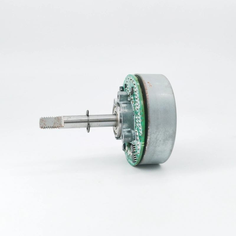
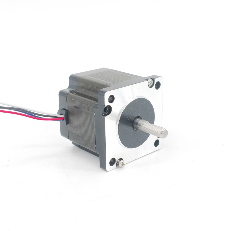
A DC motor can stably convert direct current into rotational mechanical energy, primarily by addressing the issue of “unidirectional magnetic field” generated by direct current through a special structural design. It relies on a “commutator” to maintain a consistent direction of the rotor’s 受力 (force) , and its operation involves three core components—stator, rotor, and commutator—as well as two key processes: directional electromagnetic force action and mechanical commutation. The specific principle can be broken down into the following three parts:
1. Core Components: Building the “Structural Framework” for Directional Force
The structural design of a DC motor is centered around the need for “continuous rotation,” with each of the three components serving a distinct purpose:
- Stator: As the fixed part of the motor, it mainly consists of main magnetic poles, a frame, and brushes. The main magnetic poles are usually wound with field windings; when direct current is passed through them, a constant magnetic field (with alternating N and S poles) is generated, providing an environment for the rotor to experience force. The brushes are fixed on the frame—one end is connected to an external DC power supply, and the other end is in contact with the rotor’s commutator, responsible for transmitting current to the rotor.
- Rotor (Armature): Located within the stator’s magnetic field, it can rotate around the motor shaft and is composed of an armature core and armature windings. The armature core is made by stacking silicon steel sheets to reduce eddy current losses. The armature windings are wound in the slots of the core according to a specific pattern and serve as the core component for generating electromagnetic force through the interaction between current and magnetic field.
- Commutator: A “key innovation” of DC motors, it is fixed on the rotor shaft and connected to both ends of the armature windings. It is composed of multiple insulated copper segments (the number of copper segments matches the number of turns in the armature windings) . Acting as a “current direction converter,” it changes the direction of current in the armature windings in real time through sliding contact with the brushes.
2. Operating Mechanism: The “Core Logic” for Achieving Continuous Rotation
The rotation of a DC motor depends on the synergy between “electromagnetic force generation” and “commutator adjustment,” with the specific process divided into two steps:
- Directional Generation of Electromagnetic Force: When external direct current flows into the commutator through the brushes and then into the armature windings, the conductors of the armature windings—located in the stator’s constant magnetic field—experience electromagnetic force in accordance with Fleming’s Left-Hand Rule. For example, conductors below the stator’s N pole experience a force to the right, while those below the S pole experience a force to the left. These forces collectively form an electromagnetic torque that drives the rotor to rotate clockwise.
- Commutation Function of the Commutator: When the rotor rotates to the point where “the conductors of the armature windings cross the center line of the stator’s magnetic poles,” if the current direction remains unchanged, the direction of the magnetic field acting on the conductors will reverse, causing the direction of the electromagnetic force to reverse and preventing the rotor from rotating continuously. At this point, the commutator rotates synchronously with the rotor. Through the switching of contact between the copper segments and the brushes, it precisely reverses the current direction in the conductor—current that was originally flowing in now flows out—maintaining the same direction of the electromagnetic force (still driving the rotor to rotate clockwise) . This cycle repeats: every time the rotor rotates 180°, the commutator adjusts the current direction once, ensuring the rotor always receives an electromagnetic torque in the same direction and enabling continuous rotation.
3. Practical Significance of the Principle: Determining the Performance and Applications of DC Motors
This core principle endows DC motors with unique advantages: by adjusting the armature voltage or field current, smooth speed regulation (e.g., continuous variation from low to high speed) can be easily achieved. Additionally, they have a high starting torque, allowing them to start heavy-load equipment. Therefore, DC motors are widely used in scenarios requiring high precision in speed control, such as spindle drives for machine tools and elevator traction machines in the industrial sector, drive systems for traditional electric vehicles in the transportation sector, and power tools and treadmill motors in household appliances. However, due to the mechanical friction between the commutator and brushes, DC motors have relatively higher maintenance costs and a shorter lifespan compared to AC motors. This has also driven the development of brushless DC motors (which use electronic commutation instead of mechanical commutation) .


